- 您现在的位置:买卖IC网 > Sheet目录1253 > XR16M890IL32-0C-EB (Exar Corporation)BOARD EVAL XR16M890IL32
�� �
�
�XR16M890�
�UART� WITH� 128-BYTE� FIFO� AND� INTEGRATED� LEVEL� SHIFTERS�
�REV.� 1.0.0�
�1.14�
�Auto� Xon/Xoff� (Software)� Flow� Control�
�When� software� flow� control� is� enabled� (� See� Table� 18� ),� the� M890� compares� one� or� two� sequential� receive� data�
�characters� with� the� programmed� Xon� or� Xoff-1,2� character� value(s).� If� receive� character(s)� (RX)� match� the�
�programmed� values,� the� M890� will� halt� transmission� (TX)� as� soon� as� the� current� character� has� completed�
�transmission.� When� a� match� occurs,� the� Xoff� (if� enabled� via� IER� bit-5)� flag� will� be� set� and� the� interrupt� output�
�pin� will� be� activated.� Following� a� suspension� due� to� a� match� of� the� Xoff� character,� the� M890� will� monitor� the�
�receive� data� stream� for� a� match� to� the� Xon-1,2� character.� If� a� match� is� found,� the� M890� will� resume� operation�
�and� clear� the� flags� (ISR� bit-4).�
�Reset� initially� sets� the� contents� of� the� Xon/Xoff� 8-bit� flow� control� registers� to� a� logic� 0.� Following� reset� the� user�
�can� write� any� Xon/Xoff� value� desired� for� software� flow� control.� Different� conditions� can� be� set� to� detect� Xon/�
�Xoff� characters� (� See� Table� 18� )� and� suspend/resume� transmissions.� When� double� 8-bit� Xon/Xoff� characters�
�are� selected,� the� M890� compares� two� consecutive� receive� characters� with� two� software� flow� control� 8-bit�
�values� (Xon1,� Xon2,� Xoff1,� Xoff2)� and� controls� TX� transmissions� accordingly.� Under� the� above� described� flow�
�control� mechanisms,� flow� control� characters� are� not� placed� in� the� RX� FIFO.�
�In� the� event� that� the� receive� buffer� is� overfilling� and� flow� control� needs� to� be� executed,� the� M890� automatically�
�sends� an� Xoff� message� (when� enabled)� via� the� serial� TX� output� to� the� remote� modem.� The� M890� sends� the�
�Xoff-1,2� characters� two-character-times� (=� time� taken� to� send� two� characters� at� the� programmed� baud� rate)�
�after� the� receive� FIFO� crosses� the� programmed� trigger� level.� To� clear� this� condition,� the� M890� will� transmit� the�
�programmed� Xon-1,2� characters� as� soon� as� receive� FIFO� is� less� than� one� trigger� level� below� the� programmed�
�trigger� level.� Table� 5� below� explains� this� when� the� Trigger� Table-C� (� Table� 10� )� is� selected.�
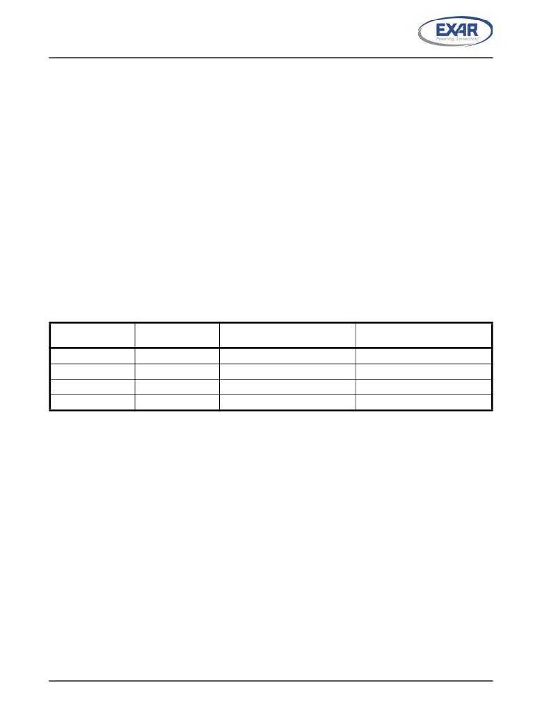
�T� ABLE� 5:� A� UTO� X� ON� /X� OFF� (S� OFTWARE� )� F� LOW� C� ONTROL�
�RX� T� RIGGER� L� EVEL�
�8�
�16�
�56�
�60�
�INT� P� IN� A� CTIVATION�
�8�
�16�
�56�
�60�
�X� OFF� C� HARACTER� (� S� )� S� ENT�
�(� CHARACTERS� IN� RX� FIFO� )�
�8*�
�16*�
�56*�
�60*�
�X� ON� C� HARACTER� (� S� )� S� ENT�
�(� CHARACTERS� IN� RX� FIFO� )�
�0�
�8�
�16�
�56�
�*� After� the� trigger� level� is� reached,� an� xoff� character� is� sent� after� a� short� span� of� time� (=� time� required� to� send� 2� characters);�
�for� example,� after� 2.083ms� has� elapsed� for� 9600� baud� and� 10-bit� word� length� setting.�
�1.15�
�Special� Character� Detect�
�A� special� character� detect� feature� is� provided� to� detect� an� 8-bit� character� when� bit-5� is� set� in� the� Enhanced�
�Feature� Register� (EFR).� When� this� character� (Xoff2)� is� detected,� it� will� be� placed� in� the� FIFO� along� with� normal�
�incoming� RX� data.�
�The� M890� compares� each� incoming� receive� character� with� Xoff-2� data.� If� a� match� exists,� the� received� data� will�
�be� transferred� to� the� RX� FIFO� and� ISR� bit-4� will� be� set� to� indicate� detection� of� special� character.� Although� the�
�Internal� Register� Table� shows� Xon,� Xoff� Registers� with� eight� bits� of� character� information,� the� actual� number� of�
�bits� is� dependent� on� the� programmed� word� length.� Line� Control� Register� (LCR)� bits� 0-1� defines� the� number� of�
�character� bits,� i.e.,� either� 5� bits,� 6� bits,� 7� bits,� or� 8� bits.� The� word� length� selected� by� LCR� bits� 0-1� also�
�determines� the� number� of� bits� that� will� be� used� for� the� special� character� comparison.� Bit-0� in� the� Xon,� Xoff�
�Registers� corresponds� with� the� LSB� bit� for� the� receive� character.�
�1.16�
�Auto� RS485� Half-Duplex� Control� Operation�
�The� auto� RS485� half-duplex� direction� control� feature� can� be� enabled� by� FCTR� bit� [3].� The� RTS#� pin� becomes�
�the� half-duplex� control� output� when� this� feature� has� been� enabled.� The� RTS#� pin� is� typically� connected� to� both�
�the� Driver� Enable� (DE)� and� Receiver� Enable� (RE)� of� an� RS-485� transceiver.� When� the� Transmitter� is� idle,� the�
�RTS#� pin� is� de-asserted� so� that� the� RS-485� driver� is� disabled� and� the� RS-485� receiver� is� enabled.� When� data�
�is� loaded� into� the� TX� FIFO,� the� RTS#� pin� is� asserted� to� enable� the� RS-485� driver� and� disable� the� RS-485�
�receiver.� This� changes� the� transmitter� empty� interrupt� to� TSR� empty� instead� of� THR� empty.�
�22�
�发布紧急采购,3分钟左右您将得到回复。
相关PDF资料
XR18W750/753-0B-EB
EVAL BOARD FOR XR18W750/753
XRP2526EVB
BOARD EVAL POWER SWITCH XRP2526
XRP2528EVB
BOARD EVAL POWER SWITCH XRP2528
XT800SM
GAS TRIGGER TUBE 800V SMD
YMCRPR8C25
REF PLATFORM MOTOR CTRL R8C/25
ZB3251
INLINE FUSE HOLDER PLASTIC BODY
ZB3260
INLINE FUSE HOLDER BAKELITE BODY
ZB3270
PANEL MOUNT FUSE HOLDER
相关代理商/技术参数
XR16M890IL32-F
功能描述:UART 接口集成电路 1-Ch 8 Bit/VLIO UART w/Lvl Shftrs & 4GPIO
RoHS:否 制造商:Texas Instruments 通道数量:2 数据速率:3 Mbps 电源电压-最大:3.6 V 电源电压-最小:2.7 V 电源电流:20 mA 最大工作温度:+ 85 C 最小工作温度:- 40 C 封装 / 箱体:LQFP-48 封装:Reel
XR16M890IL32TR
制造商:EXAR 制造商全称:EXAR 功能描述:UART WITH 128-BYTE FIFO AND INTEGRATED LEVEL SHIFTERS
XR16M890IL32TR-F
功能描述:UART 接口集成电路 1-Ch 8 Bit/VLIO UART w/Lvl Shftrs & 4GPIO
RoHS:否 制造商:Texas Instruments 通道数量:2 数据速率:3 Mbps 电源电压-最大:3.6 V 电源电压-最小:2.7 V 电源电流:20 mA 最大工作温度:+ 85 C 最小工作温度:- 40 C 封装 / 箱体:LQFP-48 封装:Reel
XR16M890IL40
制造商:EXAR 制造商全称:EXAR 功能描述:UART WITH 128-BYTE FIFO AND INTEGRATED LEVEL SHIFTERS
XR16M890IL40-0C-EB
功能描述:UART 接口集成电路 EVAL F/M890 QFN40 MOT, INTEL, VLIO INT RoHS:否 制造商:Texas Instruments 通道数量:2 数据速率:3 Mbps 电源电压-最大:3.6 V 电源电压-最小:2.7 V 电源电流:20 mA 最大工作温度:+ 85 C 最小工作温度:- 40 C 封装 / 箱体:LQFP-48 封装:Reel
XR16M890IL40-F
功能描述:UART 接口集成电路 1-Ch 8 Bit/VLIO UART w/Lvl Shftrs & 8GPIO
RoHS:否 制造商:Texas Instruments 通道数量:2 数据速率:3 Mbps 电源电压-最大:3.6 V 电源电压-最小:2.7 V 电源电流:20 mA 最大工作温度:+ 85 C 最小工作温度:- 40 C 封装 / 箱体:LQFP-48 封装:Reel
XR16M890IL40TR
制造商:EXAR 制造商全称:EXAR 功能描述:UART WITH 128-BYTE FIFO AND INTEGRATED LEVEL SHIFTERS
XR16M890IL40TR-F
功能描述:UART 接口集成电路 1-Ch 8 Bit/VLIO UART w/Lvl Shftrs & 8GPIO
RoHS:否 制造商:Texas Instruments 通道数量:2 数据速率:3 Mbps 电源电压-最大:3.6 V 电源电压-最小:2.7 V 电源电流:20 mA 最大工作温度:+ 85 C 最小工作温度:- 40 C 封装 / 箱体:LQFP-48 封装:Reel